Category: Instrumentation

Evaluation of Occupancy / Motion Sensors for Perimeter Security

— Work in Progress —

I am evaluating range, sensitivity, immunity from false triggering, and power requirements, for various projects around the house. In particular, I would like to be notified when a person or a vehicle comes down my driveway, so I can light the way if it’s dark.

Sensors Considered

  1. Passive Infrared (PIR)
    1. AM312 3.3 or 5V, active low
    2. SB0072 Futurelec MINI_PIR_MOD_B 5-20V, adjustable delay time
  2. Microwave Doppler
    1. RCWL-0516
    2. RCWL-9192
  3. Ultrasonic (SONAR)
    1. RCWL-1655 board and waterproof ultrasonic distance sensor

TLDR;

PIR produces many false triggers with sunlight and moving foliage.

Microwave Doppler is pretty short-range

Ultrasonic is pretty short-range

Testing

Passive Infrared (PIR)

Microwave Doppler

Ultrasonic (SONAR) – RCWL-1655

Range: Quoted as up to 5 meters; detects humans up to about 1.5 meters

Immunity from false triggering: Once I filtered out zero-responses, I only see false triggering when there is a target too small or too far away to reliably register.

Power requirements: Currently testing with a 1500 mAh LiPo battery; started the test on 2024-09-22 at 21:00 or so.

Test routine:

  • take a reading “ping”
  • if result is different than before, take repeated readings until two in a row match within 10%
  • if this new “clean” reading is different than before, report it with a JSON message transmitted via LoRa
  • sleep for 0.25 seconds (originally 1 second). Since the processing takes 120ms or so, sleeping for 250ms cuts power consumption by perhaps two thirds.

Seismometer Project

A friend asked me if I had a seismometer. Nope. But I might be able to build one…

One approach would be to build a more traditional weight-and-spring kind of thing, but I thought I could do it more easily with a MEMS accelerometer. I had one laying around, so I decided to try it out.

I hooked up an LSM303DLH 6DOF accelerometer/magnetometer to an ESP-01 running an ESP8266 processor. It worked, but the update rate was below the sampling rate that I will need for future frequency spectrum analysis, so I switched to a piezoelectric disk for the sensor.

I used an online ASCII drawing program which allows me to put a block diagram into the source files for handy reference.

                                   ┌──────────────┐ 
piezo ──► amp ───► ATmega ───────► │ESP-01 AP-STA │ 
                   fast loop       │  MQTT        │ 
                                   │ HTML         │ 
                                   └──────────────┘

There are four main components:

  1. The piezoelectric element. This crystal develops a high voltage when deformed, but at an extremely low current, and thus requires amplification. In order to deform the piezo crystal, I hot-glued a large nut to the top as an inertial mass. The crystal will sit on a surface that presumably moves with the shaking of the earth. NOTE: “real” seismometers, or geophones, are intended to sense earthquakes whose period of motion extends into the hundreds of seconds. There is no way this sensor will measure those, but it has recorded  motions caused by footfalls, distant fireworks, and thunderstorms.

    The piezoelectric element, with its inertial mass, on a concrete basement floor.
  2. The preamplifier. I started with the circuit given here (thank you!), and modified it for my particular needs. Here is its schematic:
    piezo_preamp I developed the schematic and the PCB using KiCad, and had the boards produced by JLCPCB. Warning note: do allow search autocompletion from “kicad” to “http://www.kicad-pcb.org/” – somebody has bought that domain and it might be evil.

    The preamplifier board
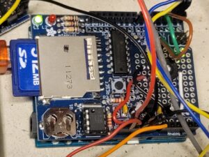
  3. The sampling system. A program running on an Arduino UNO which samples the voltage provided by the preamplifier, compares it to a threshold value set by a potentiometer, and records any samples that exceed the threshold to an SD card. The SD card, potentiometer, and RTC (real-time clock) are provided on a data-logging shield. The sampled values are also provided to the ESP8266.
    Note the messy wiring of this prototype!
    The (messy prototype) sampling system under the data-logging shield
  4. The ESP8266. A program running on a ESP-01 receives sample values via a serial pin from the sampling system. The sampled values are distributed to MQTT connected by WiFi. They are also provided to a web page served by this same ESP-01 (see below for a screen shot of this web page.) The ESP-01 also provides a hot-spot so that it can serve the web page even if it’s not attached to a host WiFi (although then it will not be able to send MQTT messages!)

    The ESP-01 on a convenient programming board

There are a few points of interest / investigation in this project:

  • What is the frequency response of this kind of accelerometer?
  • What are the frequencies of interest to this friend?
  • What sampling rates are possible for this device?
  • How to filter / smooth the raw data
  • Is calibration required?
  • How to present the data?

The web page

In this post, I’m just going to address one possibility for the last item. I log the data with timestamps into a file on a µSD card, but I also want to see the data, in real time, with some history.

Here’s a screen shot of the web page. The chart is provided using Google charts. The chart is updated every 5 seconds via a websocket connection.

After taking the screen shot, I added annotations to indicate some different types of activity that were recorded.

The web page is restricted to my home network, but you are welcome to the code. I have broken the HTML code out into a separate file for ease in editing, but named it with a .cpp extension because the Arduino IDE software won’t include a file with an extension of “.html” 🙁

Takeaways

  1. Don’t use reeeeallly tiny components if you don’t need to. The diodes I used in the preamplifier are SOD-523, 1.2 x 0.8 mm. These were far too small. I needed a magnifying glass to see the orientation, and the heat gun several times blew them off the board. Even 0805 (2.0 x 1.2 mm) are smaller than I want to handle in future projects. I’m thinking that 1206 (3.2 x 1.6 mm) is about right.
  2. Think of your off-board connections. It is common to configure battery-operated audio devices so that the 2-wire input plug (TS) goes to a 3-input (TRS) jack; the shaft connects to the ground network of the board, while the ring is connected to the battery’s negative terminal. When a TS plug is inserted, its shaft shorts the jack’s ring to its shaft, and thus the circuit is completed. I set up this board, now at revision 3, with that in mind. But I didn’t make provisions for powering the board from a bench supply during testing, and that caused a small amount of unnecessary extra work.

Chuck’s SDP Links

Articles especially pertinent to Senior Design Projects

Please share the problems you encounter!

U.Illinois Robotic Systems book – work in progress. In particular, this book already has nice sections on forward and reverse kinematics.

Switching Mains Power – not fully investigated yet. A place to start your investigation.

Sonoff S31 Mains Power Switches

Sonoff S40 Mains Power Switches

Adafruit Power Relay Module

Surface-mount soldering tutorial

“Ideal Diodes”: Protect Your Project from Reversed Polarity Power

Don’t use Nyquist as your only criterion for choosing a sampling rate

RP2040 resources from Cornell from their microprocessor design course ECE 4760

Wearable sensor for continuous analysis of sweat

Astrophotography and the new HD Raspberry Pi Camera

Raspberry Pi HD Camera for astrophotography

AstroPitography | Dr Adam Luke Baskerville

My DIY 8″ Telescope & Raspberry Pi HQ Camera

Astrophotography with Raspberry Pi HQ Camera and Celestron Astromaster 130 EQ

New Pi camera – any good for Astrophotography?

I2CWrapper – Using microcontrollers to translate I2C for non-I2C devices

System for digital signing of photographs

… and breaking the system for digital signing of photographs

Forest-deployed wildfire sensing and reporting system

New series of ATtiny µP eliminates requirement for dedicated pins


Blogs and Vlogs


Engineering, specifically EE, CompE

Eric Bogatin – Practical EE/CompE fundamentals and practical skills

Andreas Spiess – LoRa, low-power, sensor networks, ESP8266, ESP32

David Jones – EEVblog; instrumentation, troubleshooting, repair

Bil Herd – electrical engineer, designer at Commodore; CPLD, PLL

Moritz Klein – Audio electronics

Fran Blanche – FranLab; Apollo flight computer, DSKY, FranTone audio pedals

Big Clive – tear-downs

Ben Krasnow – Applied Science; including electronics; how he built his own electron microscope

Alan [w2aew] – tutorials on components; ham radio; RF


Security

Steve Gibson – Security Now podcast – a MUST for computer security folks; good episodes on internet components


Science & Math

Michael Stevens – Vsauce, The Mind Field

Grant Sanderson – 3Blue1Brown; math concepts, including a good visualization of Fourier analysis

Ben Sparks, Holly Krieger – Numberphile; math concepts, including large numbers and number theory

Matt Parker – Stand-Up Maths, lectures at Royal Institution

Brady Heywood – Understanding Complexity, complexity theory

Grady Hillhouse – Practical Engineering, particularly civil engineering

Collin Cunningham – “Lab Notes”, quick videos about electrical components and Adafruit products


Making, Robots, and Machinery

Adam Savage – amazing maker, MythBusters

Simone Giertz – general making, silly projects

Jeremy Fielding – general EE topics; built a cool robot arm

Tim Hunkin – very fun arcade game maker – machining tips


Other Sites of Topical Interest

The Cave Pearl Project – remote underwater sensing; excellent documentation of battery systems, sensors, builds

Interesting circuit uses only two wires for power and status (not TWI)

Comparison of manufacturers of PCBs in small quantities (incl. PCBWay, OSHPark, and JLCPCB)

How to use a thermal camera to troubleshoot electronics projects

Car security systems

Failures are important, and sharing them is more so

An interesting cascade of failures

NASA failure analysis

More NASA failure analysis

Mechanical analog fire-control computers

FloodNet – distributed flood sensing system for NYC

Arduino debugging

Acoustic detection of water leaks

Circuit board for a differential oscilloscope probe

Three designs for bidirectional voltage level shifting

Orange Pi 3b vs. Raspberry Pi

Battery monitoring

Introduction to Kalman Filters, useful for combining data from multiple sources

Ongoing project documentation

(Mis)using LoRa nodes to sense soil moisture

Mechanical neural network

Microphone array to isolate individual voices

Interesting uses of diodes

The Matter IoT Standard

Using the Matter protocol on ESP32

Building or buying contact piezo microphones


Internet Black Hole – Danger!

Destin Sandlin – SmarterEveryDay; how stuff works, including helicopters, nuclear subs, the James Webb space telescope

Derek Muller (PhD Physics) – Veritasium

Mark Rober – e.g. squirrel obstacle course, glitter bomb, world’s smallest Nerf gun

Markus Voelter – Omega Tau podcast; aviation, gliders, rides in fighters. Half of his podcasts are in English; the other half in German


Scary (but interesting) stuff – Don’t do this at home (nor at M5, nor for SDP)!!!

Mehdi Sadaghdar – ElectroBOOM; high-voltage stuff; fun to watch

Colin Furze – crazy powerful builds

Plasma Channel – plasma thrusters

Styro Pyro – big scary lasers


Apparatus to monitor the cycling of the hot tub pump

It’s working.

I may be having a problem with my hot tub pump – it’s running with shorter cycles than I remember it. That’s better for close temperature control, but worse for stress on the motor.
I had a problem with the pump’s computer unit once before – it was overheating and cycling more and more rapidly. So now I want to monitor it to see if its cycling is getting faster.

I can’t monitor it using a current sensor, since those ones I have are rated for 10A at 120V, while the motor unit uses 15A at 120V.

So I built a monitoring system – weather sealed a 1″ piezo disk, breadboarded a JFET amplifier for it, connected it to an ESP8266 microcontroller which I programmed to take readings at 480Hz, dot-product out the components at 60Hz and 120Hz (which for some reason is stronger) and send them via WiFi to my MQTT server, from which I scoop them with a Perl script to a log file (for now). I’ve determined the best discriminant between non-running and running with a z-score of 6.6+ from each, so I know it’s pretty good.
Now I can relax for a while while the data accumulates…

Data from the 60Hz and 120Hz dot-products:

7-Dec-2021 14:02:18: home/hot_tub_motor/a02/value/couplet -> 32.839 16.014
7-Dec-2021 14:02:24: home/hot_tub_motor/a02/value/couplet -> 29.103 16.061
7-Dec-2021 14:02:29: home/hot_tub_motor/a02/value/couplet -> 29.301 16.638
7-Dec-2021 14:02:35: home/hot_tub_motor/a02/value/couplet -> 32.062 17.769
7-Dec-2021 14:02:40: home/hot_tub_motor/a02/value/couplet -> 28.854 16.440
7-Dec-2021 14:02:45: home/hot_tub_motor/a02/value/couplet -> 33.069 16.328
7-Dec-2021 14:02:51: home/hot_tub_motor/a02/value/couplet -> 28.665 17.092
7-Dec-2021 14:02:56: home/hot_tub_motor/a02/value/couplet -> 28.019 18.892
7-Dec-2021 14:03:03: home/hot_tub_motor/a02/value/couplet -> 32.541 17.647
7-Dec-2021 14:03:07: home/hot_tub_motor/a02/value/couplet -> 29.323 16.411
7-Dec-2021 14:03:12: home/hot_tub_motor/a02/value/couplet -> 69.411 58.708
7-Dec-2021 14:03:17: home/hot_tub_motor/a02/value/couplet -> 38.942 56.288
7-Dec-2021 14:03:24: home/hot_tub_motor/a02/value/couplet -> 16.419 50.588
7-Dec-2021 14:03:32: home/hot_tub_motor/a02/value/couplet -> 25.903 59.193
7-Dec-2021 14:03:33: home/hot_tub_motor/a02/value/couplet -> 70.220 61.097
7-Dec-2021 14:03:40: home/hot_tub_motor/a02/value/couplet -> 60.011 61.728
7-Dec-2021 14:03:44: home/hot_tub_motor/a02/value/couplet -> 17.743 51.550
7-Dec-2021 14:03:49: home/hot_tub_motor/a02/value/couplet -> 37.571 57.612
7-Dec-2021 14:03:55: home/hot_tub_motor/a02/value/couplet -> 72.898 57.997
7-Dec-2021 14:04:00: home/hot_tub_motor/a02/value/couplet -> 23.630 55.861
7-Dec-2021 14:04:06: home/hot_tub_motor/a02/value/couplet -> 41.698 62.395
7-Dec-2021 14:04:11: home/hot_tub_motor/a02/value/couplet -> 56.960 59.568
7-Dec-2021 14:04:18: home/hot_tub_motor/a02/value/couplet -> 15.589 50.445
7-Dec-2021 14:04:22: home/hot_tub_motor/a02/value/couplet -> 71.046 62.314
7-Dec-2021 14:04:27: home/hot_tub_motor/a02/value/couplet -> 16.098 46.108
7-Dec-2021 14:04:32: home/hot_tub_motor/a02/value/couplet -> 70.857 61.175
7-Dec-2021 14:04:39: home/hot_tub_motor/a02/value/couplet -> 16.661 53.204
7-Dec-2021 14:04:45: home/hot_tub_motor/a02/value/couplet -> 73.267 63.262
7-Dec-2021 14:04:48: home/hot_tub_motor/a02/value/couplet -> 14.290 54.907
7-Dec-2021 14:04:54: home/hot_tub_motor/a02/value/couplet -> 70.185 61.067
7-Dec-2021 14:05:01: home/hot_tub_motor/a02/value/couplet -> 22.880 57.029
7-Dec-2021 14:05:06: home/hot_tub_motor/a02/value/couplet -> 51.657 55.721
7-Dec-2021 14:05:10: home/hot_tub_motor/a02/value/couplet -> 47.116 61.623

The hot tub motor started up at 14:03:12.

Data discriminated into “off” and “on”:

About to subscribe to topic 'home/hot_tub_motor/a02/status'
7-Dec-2021 14:42:21: home/hot_tub_motor/a02/status -> 0
7-Dec-2021 14:52:23: home/hot_tub_motor/a02/status -> 1
7-Dec-2021 15:03:02: home/hot_tub_motor/a02/status -> 0

I’m not sure why the vibration is at 120Hz and not at 60Hz. I’ll have to think about AC motors and how they operate now.

Yay! Another investigation!

Watchdog watchdog

Well. It’s been a while. Here’s what’s new:

I monitor my heating system (temperatures, zone activation) with an Arduino, and relay the values to my home monitoring system through an ESP-01 / ESP8266. The Arduino occasionally hangs up.

I have tried to fix this by checking the power supply for good clean power; by making it reboot itself every 24 hours; by enabling the ATmega328’s watchdog timer. It still hangs up.

When it is running, it flashes an LED connected to the standard pin 13 of the Arduino. I recalled seeing that a 555 timer could be used as a missing-pulse detector. This would trigger if the 1Hz flashing stops. Cool. The missing pulse detector takes its output low during pulse starvation, and takes it high during the happy times when the pulses continue. I needed to take that prolonged low value and turn it into a one-shot pulse to drop and resume the power to the Arduino, and a second 555 could be configured as a one-shot to create this pulse. I had to add a capacitor in between to prevent continuous retriggering of the second 555, which would keep the power off to the Arduino.

The circuit “1” in the schematic illustrates this setup.

I happened to have a 556 handy, which comprises the functionality of two 555 timers. The equivalent simpler circuit is “2” in the schematic.

But, duh. I’m really more of a programmer at heart. And I had some ATtiny85 chips around. So I created an Arduino program to embody all the above functionality in a much simpler circuit – “3” in the schematic.

Note: in the code and the schematic the name ATmega refers to the (processor on the) Arduino board.

Watchdog_watchdog_sch

And I put it all onto a very small solderless breadboard. Since I needed regulated 5V to feed all the components, I put standard voltage regulation onto the breadboard as well.

The Arduino program was very simple:


/*
  Watchdog_watchdog
  
  One of my Arduinos, the one that monitors temperatures and zone activations 
  in my heating system, occasionally hangs up. This despite the fact that I'm
  using the ATmega watchdog to automatically reset it if it hangs. Dunno why. 
  The power seems good and stable. I've tried replacing the ATmega chip.

  I've decided to kill a flea with a cannon. The ATmega blinks an LED at 1Hz
  to indicate that it's still alive - I call this a throbber. The ATtiny will 
  monitor the throbber and if it stops, it will power-cycle the ATmega.
  Hah.

  The MOSFET in question will be a p-channel MOSFET configured on the high side
  of the power to the ATmega; when its gate is pulled low, it allows power to 
  flow to the ATmega. The specific MOSFET I'm using is a 5LP01SP, which is a 
  p-channel device whose pins are 1=source, 2=drain, 3=gate.
  
*/

#define pdThrobber_in 3
#define pdMOSFET      4

const unsigned long resetAfter_ms = 2000UL;
unsigned long lastThrobAt_ms = 0UL;


void setup() {
  pinMode ( pdThrobber_in, INPUT );
  pinMode ( pdMOSFET, OUTPUT );
}

void loop() {
  static int throbberStatePrevious = 0;
  int throbberState = digitalRead ( pdThrobber_in );
  if ( throbberState != throbberStatePrevious ) {
    lastThrobAt_ms = millis();
    throbberStatePrevious = throbberState;
  }
  if ( ( millis() - lastThrobAt_ms ) > resetAfter_ms ) {
    // BOOM. Cause a reset
    digitalWrite ( pdMOSFET, 1 );  // turns off ATmega
    delay ( 500 );
    digitalWrite ( pdMOSFET, 0 );
    delay ( 5000 );  // time enough to let the ATmega boot up
    lastThrobAt_ms = millis();  // reset the watchdog
  }
}

EBD-USB+ Electronic Load – Testing Power Supplies and Batteries

I watched a video from Andreas Speiss reviewing electronic loads, and identifying one in particular called EBD-USB+ from zketech.com and purchased through Amazon or Banggood or wherever. The software is a little hard to find, but it’s available through this link. It comes as a .rar file, which you might need to unpack with 7-zip or Winzip. You will also need the driver.

[Read More...]

Calculating the Axis of Nutation of my Solar Tracker

Following on the cluster analysis of the last post, I pairwise crossed (as in cross-multiply) the resulting cluster centers, and got three reasonably-close vectors after normalization. These were:

0 x 1: (-0.36, 0.93, -0.10)
0 x 2: (-0.23, 0.97, -0.06)
1 x 2: (-0.20, 0.97, -0.14)

While satisfyingly close, I wanted to do better.

[Read More...]

Instrumenting and Analyzing My Solar Tracker

I’m an instrumentation and data collection geek. I love the challenge of developing ways to monitor the systems of my house and making sure they’re working properly. I’ve had a couple bad experiences where systems failed and not knowing it soon enough caused problems.

[Read More...]