A friend asked me if I had a seismometer. Nope. But I might be able to build one…
One approach would be to build a more traditional weight-and-spring kind of thing, but I thought I could do it more easily with a MEMS accelerometer. I had one laying around, so I decided to try it out.
I hooked up an LSM303DLH 6DOF accelerometer/magnetometer to an ESP-01 running an ESP8266 processor. It worked, but the update rate was below the sampling rate that I will need for future frequency spectrum analysis, so I switched to a piezoelectric disk for the sensor.
I used an online ASCII drawing program which allows me to put a block diagram into the source files for handy reference.
                                   ┌──────────────┐
piezo ──► amp ───► ATmega ───────► │ESP-01 AP-STA │
                   fast loop       │  MQTT        │
                                   │ HTML         │
                                   └──────────────┘
There are four main components:
- The piezoelectric element. This crystal develops a high voltage when deformed, but at an extremely low current, and thus requires amplification. In order to deform the piezo crystal, I hot-glued a large nut to the top as an inertial mass. The crystal will sit on a surface that presumably moves with the shaking of the earth. NOTE: “real” seismometers, or geophones, are intended to sense earthquakes whose period of motion extends into the hundreds of seconds. There is no way this sensor will measure those, but it has recorded motions caused by footfalls, distant fireworks, and thunderstorms.

The piezoelectric element, with its inertial mass, on a concrete basement floor. - The preamplifier. I started with the circuit given here (thank you!), and modified it for my particular needs. Here is its schematic:
piezo_preamp I developed the schematic and the PCB using KiCad, and had the boards produced by JLCPCB. Warning note: do allow search autocompletion from “kicad” to “http://www.kicad-pcb.org/” – somebody has bought that domain and it might be evil.

The preamplifier board - The sampling system. A program running on an Arduino UNO which samples the voltage provided by the preamplifier, compares it to a threshold value set by a potentiometer, and records any samples that exceed the threshold to an SD card. The SD card, potentiometer, and RTC (real-time clock) are provided on a data-logging shield. The sampled values are also provided to the ESP8266.
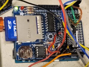
The (messy prototype) sampling system under the data-logging shield - The ESP8266. A program running on a ESP-01 receives sample values via a serial pin from the sampling system. The sampled values are distributed to MQTT connected by WiFi. They are also provided to a web page served by this same ESP-01 (see below for a screen shot of this web page.) The ESP-01 also provides a hot-spot so that it can serve the web page even if it’s not attached to a host WiFi (although then it will not be able to send MQTT messages!)

The ESP-01 on a convenient programming board
There are a few points of interest / investigation in this project:
- What is the frequency response of this kind of accelerometer?
- What are the frequencies of interest to this friend?
- What sampling rates are possible for this device?
- How to filter / smooth the raw data
- Is calibration required?
- How to present the data?
The web page
In this post, I’m just going to address one possibility for the last item. I log the data with timestamps into a file on a µSD card, but I also want to see the data, in real time, with some history.
Here’s a screen shot of the web page. The chart is provided using Google charts. The chart is updated every 5 seconds via a websocket connection.

After taking the screen shot, I added annotations to indicate some different types of activity that were recorded.
The web page is restricted to my home network, but you are welcome to the code. I have broken the HTML code out into a separate file for ease in editing, but named it with a .cpp extension because the Arduino IDE software won’t include a file with an extension of “.html” 🙁
Takeaways
- Don’t use reeeeallly tiny components if you don’t need to. The diodes I used in the preamplifier are SOD-523, 1.2 x 0.8 mm. These were far too small. I needed a magnifying glass to see the orientation, and the heat gun several times blew them off the board. Even 0805 (2.0 x 1.2 mm) are smaller than I want to handle in future projects. I’m thinking that 1206 (3.2 x 1.6 mm) is about right.
- Think of your off-board connections. It is common to configure battery-operated audio devices so that the 2-wire input plug (TS) goes to a 3-input (TRS) jack; the shaft connects to the ground network of the board, while the ring is connected to the battery’s negative terminal. When a TS plug is inserted, its shaft shorts the jack’s ring to its shaft, and thus the circuit is completed. I set up this board, now at revision 3, with that in mind. But I didn’t make provisions for powering the board from a bench supply during testing, and that caused a small amount of unnecessary extra work.